“Logic gate symbols” sit at the heart of every digital system you use today.
From your smartphone to powerful computers, these tiny visual diagrams represent how machines “think” using simple binary logic.
If you understand these symbols, you unlock the blueprint of modern electronics.
Let’s break everything down in a way that actually sticks. No fluff. Just clear, practical knowledge you can use.
What Are Logic Gate Symbols?
Simple Definition with Real Context
Logic gate symbols are graphical representations of logic gates used in digital circuits. Engineers rely on these symbols to design, analyze, and troubleshoot electronic systems.
Instead of writing long logical expressions, they draw simple shapes. Each shape represents a function like AND, OR, or NOT.
Think of it like road signs. One glance, and you instantly know what’s happening.
Why Symbols Matter in Circuit Design
Without symbols, circuit diagrams would look chaotic. Symbols bring clarity.
They help you:
- Visualize logic functions quickly
- Design integrated circuits (ICs) efficiently
- Understand data processing circuits
- Communicate designs across teams
A complex central processing unit contains billions of these logic operations. Symbols make that complexity manageable.
Binary Logic Behind Every Symbol
Every digital logic gate works on the binary system:
- 0 (LOW state) → No voltage or false
- 1 (HIGH state) → Voltage present or true
Each symbol defines how inputs (0s and 1s) turn into outputs.
For example:
- Input: 1 and 1
- Output: depends on the gate
That simple rule powers the entire digital world.
Foundation of Logic Gates
Boolean Algebra and Logic Functions
At the core lies Boolean algebra. It defines how logic works mathematically.
Key operations include:
- Logical conjunction (AND)
- Logical disjunction (OR)
- Negation function (NOT)
These operations form the base of all logic gate functions.
“Every digital decision is just Boolean algebra in action.”
Transistors and How Gates Are Built
A logic gate isn’t magic. It’s built using transistors.
- A single gate may use a few transistors
- Modern chips contain billions of transistors
- These are packed into silicon chips
Hierarchy looks like this:
- Transistors → Logic gates
- Logic gates → Integrated circuits
- ICs → Full digital systems
Digital vs Analog Signals
Unlike analog systems, digital systems use discrete values.
| Type | Signal Form | Example |
| Analog | Continuous | Sound waves |
| Digital | Binary (0/1) | Computers |
Voltage levels determine logic states. For example:
- 0V → LOW
- 5V → HIGH
This simplicity makes digital circuits reliable and fast.
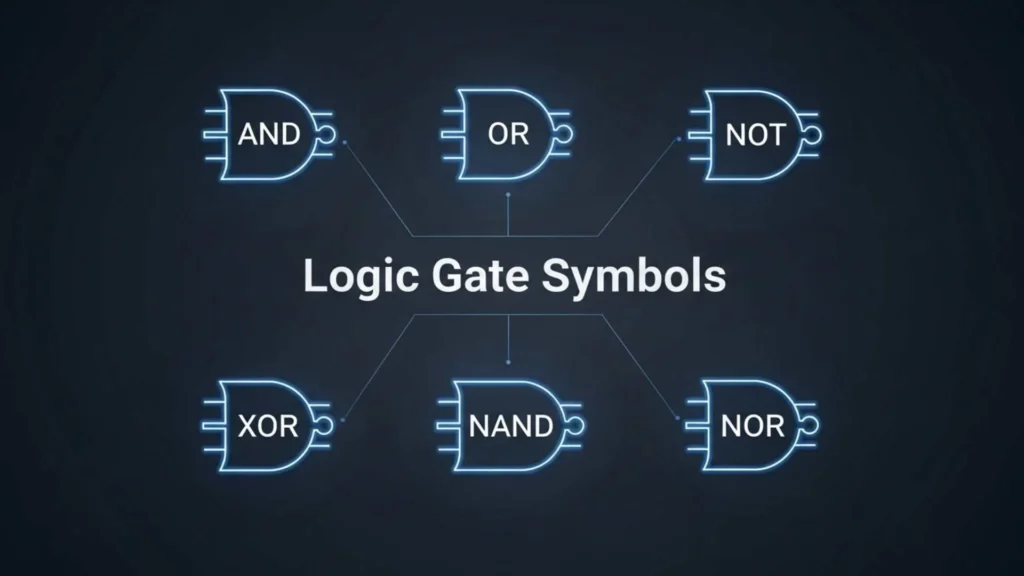
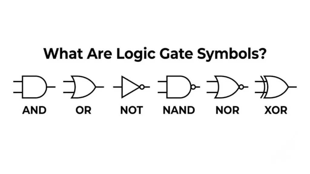
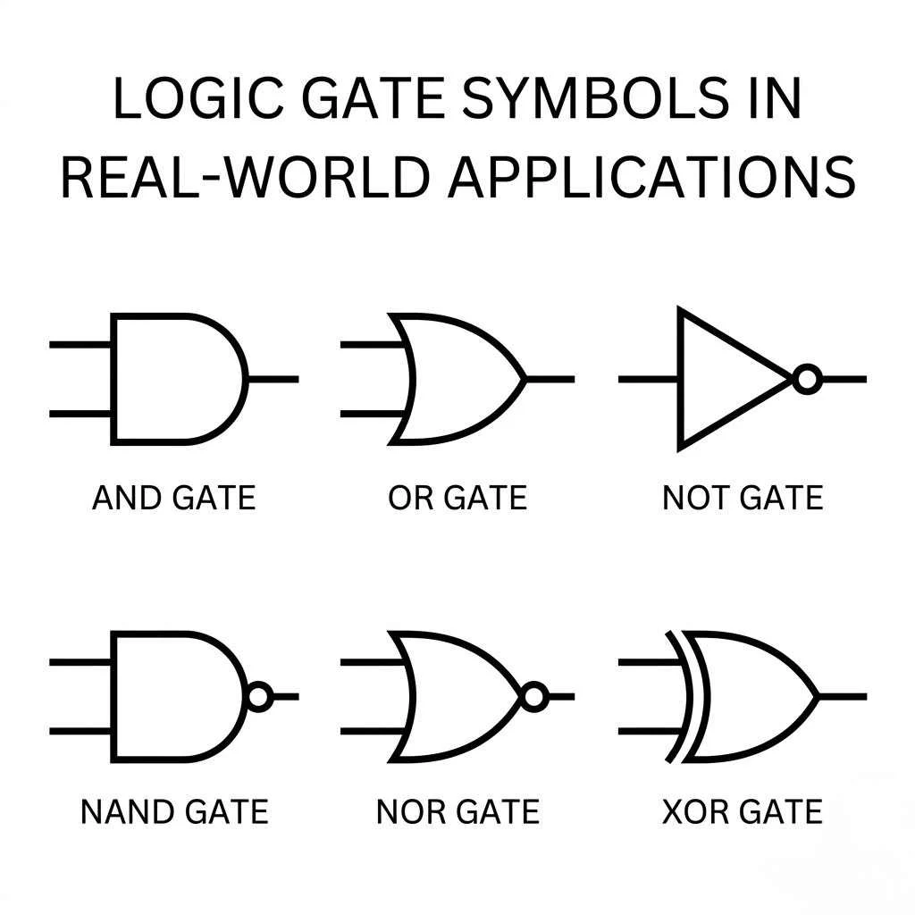
Standard Logic Gate Symbols and Their Meanings
Now let’s dive into the core of logic gate symbols.
NOT Gate Symbol
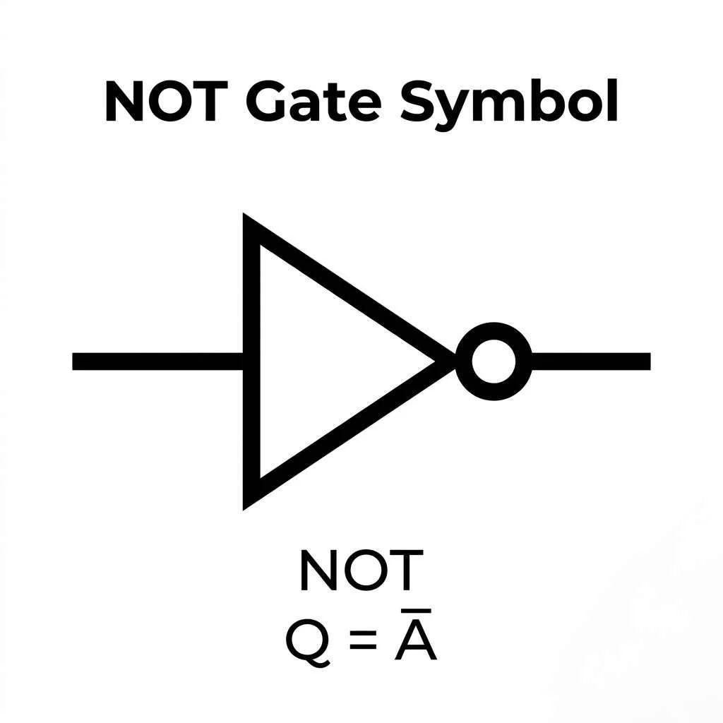
The NOT gate flips the input.
- Symbol: Triangle with a small circle
- Function: Inversion
Equation:
Y = A̅
Truth Table:
| Input (A) | Output (Y) |
| 0 | 1 |
| 1 | 0 |
Use case: Turning signals ON/OFF.
AND Gate Symbol
The AND gate outputs 1 only if all inputs are 1.
Equation:
Y = AB
Truth Table:
| A | B | Output |
| 0 | 0 | 0 |
| 0 | 1 | 0 |
| 1 | 0 | 0 |
| 1 | 1 | 1 |
This gate performs logical conjunction.
OR Gate Symbol
The OR gate outputs 1 if at least one input is 1.
Equation:
Y = A + B
Truth Table:
| A | B | Output |
| 0 | 0 | 0 |
| 0 | 1 | 1 |
| 1 | 0 | 1 |
| 1 | 1 | 1 |
It handles logical disjunction.
NAND Gate Symbol
The NAND gate is NOT + AND combined.
Equation:
Y = (AB)̅
It’s a universal gate.
Truth Table:
| A | B | Output |
| 0 | 0 | 1 |
| 0 | 1 | 1 |
| 1 | 0 | 1 |
| 1 | 1 | 0 |
NOR Gate Symbol
The NOR gate is NOT + OR.
Equation:
Y = (A + B)̅
Also a universal gate.
XOR Gate Symbol
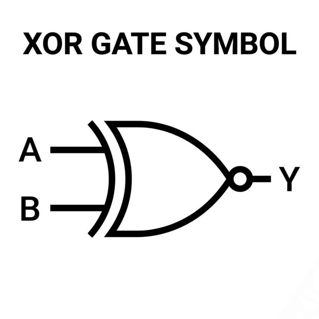
The XOR gate outputs 1 only when inputs differ.
- Known as modulo 2 sum
Truth Table:
| A | B | Output |
| 0 | 0 | 0 |
| 0 | 1 | 1 |
| 1 | 0 | 1 |
| 1 | 1 | 0 |
XNOR Gate Symbol
The XNOR gate is the opposite of XOR.
- Outputs 1 when inputs are the same
Used in comparison circuits.
Buffer Gate Symbol
A buffer gate doesn’t change the signal.
- Strengthens signal
- Improves signal transfer
Tri-State Buffer Symbol
This gate adds a third state:
- 0 → LOW
- 1 → HIGH
- Z → High impedance state
Used in:
- Bus systems
- Data sharing circuits
Logic Gate Symbols Table
| Gate | Boolean Expression | Function |
| NOT | Y = A̅ | Inversion |
| AND | Y = AB | Both inputs must be 1 |
| OR | Y = A + B | Any input is 1 |
| NAND | Y = (AB)̅ | NOT AND |
| NOR | Y = (A+B)̅ | NOT OR |
| XOR | A ⊕ B | Different inputs |
| XNOR | (A ⊕ B)̅ | Same inputs |
Truth Tables for All Logic Gate Symbols
Why Truth Tables Matter
A truth table shows every possible input combination.
It answers one question:
“What output do I get for these inputs?”
Complete Truth Table Overview
| A | B | AND | OR | NAND | NOR | XOR | XNOR |
| 0 | 0 | 0 | 0 | 1 | 1 | 0 | 1 |
| 0 | 1 | 0 | 1 | 1 | 0 | 1 | 0 |
| 1 | 0 | 0 | 1 | 1 | 0 | 1 | 0 |
| 1 | 1 | 1 | 1 | 0 | 0 | 0 | 1 |
Universal Gates and Why They Matter
NAND Gate as Universal Gate
You can build ANY logic gate using only NAND gates.
That means:
- Simpler manufacturing
- Lower cost
- Flexible design
NOR Gate as Universal Gate
Same story with NOR.
It can recreate:
- AND
- OR
- NOT
Practical Use in Circuit Design
Engineers prefer universal gates because they:
- Reduce circuit complexity
- Improve scalability
- Support large-scale systems
TTL vs CMOS Logic Gate Technologies
What is TTL (Transistor-Transistor Logic)
TTL uses bipolar transistors.
- Fast switching
- High power consumption
What is CMOS (Complementary MOS)
CMOS uses field-effect transistors (FETs).
- Low power
- Used in modern devices
Key Differences
| Feature | TTL | CMOS |
| Power Consumption | High | Very Low |
| Speed | Fast | Moderate |
| Technology | Bipolar | MOSFET |
| Usage | Legacy systems | Modern electronics |
Electrical Characteristics of Logic Gates
Voltage Levels
Typical values:
- LOW: 0–0.8V
- HIGH: 2–5V
Propagation Delay
This is the time taken for output to respond.
- Measured in nanoseconds
- Critical for high-speed systems
Power Consumption
Important for:
- Battery devices
- Efficiency
CMOS wins here.
Current Capacity and Fan-Out
Fan-out = number of inputs a gate can drive.
Higher fan-out means better performance.
Logic Gate Symbols in Real World Applications
Inside CPUs and Processors
Every processor uses billions of logic operations per second.
Digital Circuits and IC Design
Logic gates form:
- Memory units
- Arithmetic units
- Control systems
Smartphones and Embedded Systems
Your phone uses:
- Sensors
- Data processing
- Signal routing
All powered by logic gates.
Automation and Industrial Systems
Used in:
- Robotics
- Control panels
- Smart factories
How to Read and Draw Logic Gate Symbols Easily
Step-by-Step Method
- Identify inputs
- Recognize symbol shape
- Apply logic rule
- Determine output
Common Mistakes
- Confusing XOR with OR
- Ignoring inversion bubble
- Misreading signal direction
Pro Tips
- Memorize patterns, not shapes
- Practice with truth tables
- Draw circuits daily
Logic Gate Design and Circuit Connections
Inputs, Outputs, and Signal Flow
Signals move in one direction.
- Input → Gate → Output
Combining Gates into Circuits
Example:
- AND + NOT = NAND
- OR + NOT = NOR
LED Circuit Example
- Input switch controls gate
- Output lights LED
Simple yet powerful.
Advanced Concepts
Synchronous vs Asynchronous Systems
- Synchronous → uses clock signal
- Asynchronous → no clock
Clock Signals and Timing
Clock ensures:
- Coordination
- Timing accuracy
Miniaturization and Modern IC Design
Modern chips are:
- Smaller
- Faster
- More efficient
Frequently Asked Questions
What are logic gate symbols?
They are diagrams representing logic gates in digital electronics.
Why are NAND and NOR important?
They are universal gates.
What is XOR used for?
Used in encryption and comparison.
How do logic gates work in computers?
They process binary data using Boolean logic.
Conclusion
Logic gate symbols are the language of digital electronics. They turn simple binary inputs into meaningful outputs that power modern devices. Once you understand these symbols, you begin to see how computers actually work.
From basic circuits to advanced processors, everything builds on these tiny logical decisions. Keep practicing diagrams and truth tables because mastery comes with repetition.

Freddie Wood
Hi! I’m Freddie Wood, a storyteller at heart and a lifelong explorer of ideas. Writing has always been my way of making sense of the world, turning ordinary moments into stories that linger in your mind. I love blending emotions with adventure, and I’m fascinated by the way words can connect people across distances and experiences. When I’m not writing, you’ll find me wandering through nature, listening to music, or sketching out ideas for my next story. My goal is always to create books that stay with readers long after the last page.
Books by Freddie Wood:
-
The Hidden Path
-
Shadows of Tomorrow